
Filling a few cartridges by hand can make an unstable process look acceptable. Scale that same process to several hundred or several thousand units, and small differences in oil temperature, dispense position, cap timing, or hardware tolerances become visible as leaks, wet airpaths, uneven fill weights, and burnt first draws.
This guide is written for licensed processors, purchasing teams, and brands building a repeatable 510-cartridge filling workflow. It is not a universal temperature recipe. Oil formulations and cartridge designs differ, so the hardware supplier’s current instructions and your own validated SOP must control the final settings. It addresses fill-quality controls only; facility safety, personal protective equipment, licensing, and regulatory requirements belong in the processor’s own EHS and compliance programs.
Direct answer: A reliable 510 filling process keeps the oil within a validated viscosity window, dispenses down the reservoir wall without contaminating the center airpath, leaves the headspace required by the mouthpiece, caps within the hardware maker’s specified time, and allows the heating element to saturate before any powered test. Record fill weight, temperature, cap timing, and defects by lot so problems can be traced instead of guessed at.
Why a Filling SOP Matters More at Wholesale Volume
A cartridge can look simple from the outside: tank, heating element, airway, mouthpiece, base, and seals. During filling, however, all of those parts interact with the oil and with the pressure created when the mouthpiece is installed.
An inconsistent workflow can create several different defects that look similar after packaging. Oil in the airway may come from a misplaced nozzle, excessive fill volume, or pressure generated during capping. A dry or harsh first draw may point to inadequate saturation time, an oil-to-intake mismatch, or a unit that was tested while the heating element was still dry. A visible bubble at the top may be intentional headspace, oil absorbed into the atomizer, or a true short fill. Visual appearance alone cannot tell you which one occurred.
Production teams need a controlled, documented sequence that produces the same result across operators, shifts, and hardware lots.
Before Step 1: Get the Current Hardware Instructions
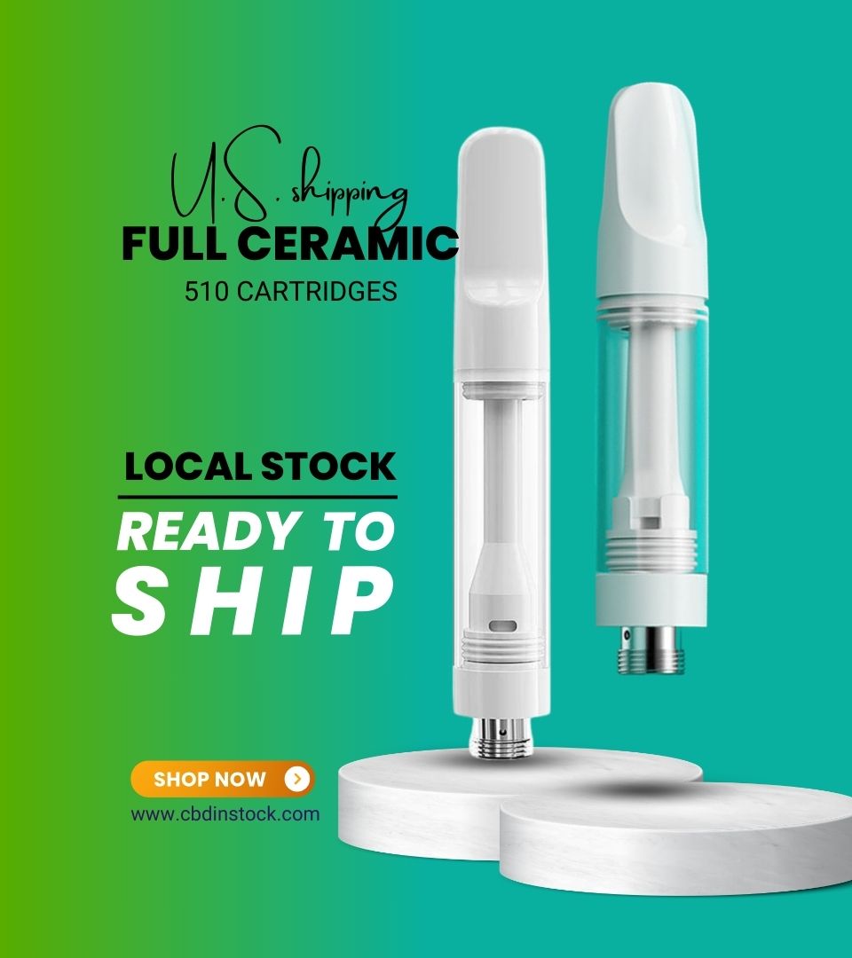
Before setting temperatures or timers, identify the exact cartridge SKU and revision. A 1ml glass 510 cartridge, a full ceramic cartridge, and a postless 510 design may require different fill positions, cap methods, fixtures, and rest periods even when all three are sold for thick oil.
If the hardware format is not yet approved, first review how to choose empty vape cartridges for thick oils; this guide begins after the cartridge type has entered process validation.
Request the following for every approved SKU:
- recommended oil-temperature or viscosity range at the point of dispense;
- compatible needle or nozzle dimensions;
- nominal capacity and permitted fill-weight tolerance;
- required headspace or maximum fill line;
- maximum time between filling and capping;
- cap method, seating depth, and press-force guidance where applicable;
- required post-fill orientation and saturation time;
- storage limits and any restrictions on reheating the hardware;
- the current drawing or specification revision.
Do not combine instructions from two similar-looking cartridges. A setting published for another supplier’s 510 cartridge is useful for planning a trial, but it is not a validated setting for your hardware.
Step 1: Condition the Oil to a Repeatable Viscosity
Temperature controls viscosity. The useful production question is: at what controlled condition can this oil be dispensed accurately without unnecessary heat exposure?
Published filling ranges vary because formulations, terpene content, tank geometry, and atomizer designs are not identical. Qualify the operating window for each formulation category and hardware combination rather than carrying one setting from distillate to live resin, rosin, or another oil type. Establish the lowest practical setting at which your equipment can meter the oil consistently, then confirm it with the cartridge manufacturer and formulation team.
Good controls include:
- Measure oil temperature at the dispense point, not only at the heater setpoint.
- Allow enough mixing or hold time for the batch to become uniform before filling.
- Define a narrow validated operating window rather than allowing operators to heat until the oil “looks thin enough.”
- Record the actual start, midpoint, and end temperatures for each batch.
- Avoid repeated heat-and-cool cycles unless your formulation team has approved them.
If fill weights begin drifting during a run, check temperature and dispense behavior before changing the target volume. Correcting a viscosity problem by increasing the dose can create overfilled cartridges once the oil returns to the intended condition.
Step 2: Prepare Cartridges, Fixtures, and the Filling Station
Bring the hardware, filling equipment, and work area into the validated environmental range before the run starts. Hardware conditioned at a different temperature may behave differently from oil metered at a fixed temperature; use pilot data to determine whether this affects your formulation and equipment.
Use a fixture that keeps every cartridge vertical and protects the 510 threads. Confirm that reservoirs are free of visible debris, cracks, chips, seal displacement, or crooked center posts. Segregate questionable units before oil is introduced; inspection is cheaper than rework.

At line clearance, verify:
- correct cartridge SKU and lot;
- correct mouthpiece and seal components;
- clean, undamaged nozzle or needle;
- calibrated balance and dispensing equipment;
- approved fill target and tolerance;
- dedicated trays for filled, capped, quarantined, and rejected units;
- batch record with operator, time, temperatures, and equipment identification.
Sample the same empty 510 vape cartridge configuration that will enter production. A mouthpiece, gasket, or intake revision can change assembly behavior even when tank capacity stays the same.
Step 3: Dispense Beside the Airpath, Not Into It
On a conventional post-style 510 cartridge, the open center tube is the airpath. Oil belongs in the annular reservoir between that tube and the outer wall. Position the nozzle close to the inside wall and dispense smoothly while keeping the tip clear of the center opening.
Three practices improve repeatability:
- Use controlled nozzle depth. A stop, guide, or fixture helps each operator place the tip at the same height without touching the atomizer or seals.
- Dispense steadily. A violent or intermittent shot can trap air, coat the chimney, or splash oil onto the sealing surface.
- Withdraw cleanly. Stop flow before lifting the nozzle so a trailing string of oil does not bridge into the airpath or onto the rim.
Postless cartridges have a different internal layout. Do not infer their fill port or nozzle depth from a center-post cart. Follow the SKU-specific drawing and verify the process with clear samples before running an opaque or decorated version.
Step 4: Control Fill by Weight and Preserve Headspace
Control net content gravimetrically: weigh the empty unit, weigh it again after filling, and calculate the difference. Nominal tank volume cannot substitute for that measurement because oil density varies and some liquid may move into the atomizer during saturation.
Headspace serves a mechanical purpose. The mouthpiece, plug, or center tube may displace volume when it is installed. Filling to the visual top of the reservoir can force oil into the airway or past a seal during capping. The correct headspace is the amount specified for that cartridge—not a universal percentage copied from another device.
Build a weight-control plan that defines:
- target net fill and acceptable tolerance;
- frequency of in-process weight checks;
- action limits for drift;
- rules for rework or rejection;
- how balances are checked during the shift;
- whether units are weighed before or after the supplier-required settling stage.
This also prevents a common customer-service mistake: treating every visible air bubble as proof of underfilling. Judge net content by the validated weight method, while separately inspecting abnormal voids, trapped bubbles, or poor saturation.
Step 5: Cap Within the Validated Time Window
Capping is part of the fluid system. Installing the mouthpiece changes internal pressure and engages the seals, so cap timing and seating must be controlled as carefully as the fill.
Some press-fit cartridges require prompt capping after filling. Some threaded designs allow a different workflow. The exact time limit, seating depth, and force must come from the manufacturer of the specific SKU.
For press-on hardware:
- Keep the mouthpiece square to the cartridge body.
- Use the correct fixture and a defined hard stop or validated press setting.
- Do not use extra force to compensate for poor alignment.
- Inspect the finished cap height against an approved reference.
- Quarantine units with tilted, proud, cracked, or visibly damaged mouthpieces.
Independent of the manufacturer’s specific seating specification, two general failure patterns apply broadly. Under-seating may leave a seal unengaged. Over-seating can deform a seal, damage a ceramic mouthpiece, or push an internal feature into the oil path. Use measured seat depth or another approved closure check; operator feel alone is too variable.
For screw-on hardware, define the approved tightening method and inspect for crossed threads, damaged seals, and oil on the mating surfaces. Hand assembly may suit sampling or small runs; larger volumes benefit from a controlled fixture or torque method if the hardware supplier supports one.
Press-On vs. Screw-On: Choose for the Line, Not Just the Look
This comparison covers filling-line tradeoffs such as speed, equipment, and rework. Oil-compatibility selection belongs in the separate empty cartridge buyer’s guide.
Press-on and screw-on closures can both work in commercial programs, but they create different operating tradeoffs.
| Production consideration | Press-on mouthpiece | Screw-on mouthpiece |
|---|---|---|
| Line speed | Can support fast repetitive capping once the press is validated | Often slower for manual assembly |
| Equipment | Usually needs an appropriate fixture or press at scale | May be assembled by hand or controlled tool, depending on design |
| Rework | Common tamper-resistant styles may not be intended to reopen | Some designs can be reopened before final disposition |
| Main process risk | Misalignment, incorrect seat depth, excessive force | Cross-threading, seal twist, inconsistent tightening |
| Best fit | Repeatable medium- or high-volume line with fixed settings | Samples, development runs, or programs valuing controlled removability |
The closure decision should be made with the filling team, not by packaging or purchasing alone. When comparing full ceramic cartridges, obtain the assembly instruction and recommended fixture before approving a mouthpiece style.
Step 6: Allow Saturation Before Powered Testing
After filling, oil needs time to migrate into the atomizer’s porous or wicking region. The required period varies with oil viscosity, intake geometry, temperature, and cartridge design. A timer copied from a consumer refill guide is not a substitute for supplier instructions and a validated production study.
Keep units in the required orientation and environmental range during this stage. Label trays with fill time and earliest permitted QC time so a busy line does not test units early. If the supplier instructs an inversion step, document its duration and use fixtures that prevent units from rolling or contacting one another.
Do not use powered firing as the first check on an unsaturated cartridge. Activating a dry heating surface can produce a harsh first draw and may scorch adjacent wicking material, degrading flavor and vapor performance. Start with visual inspection and, where your SOP permits, non-powered airflow checks. Conduct any powered test only after the required saturation period and under the sampling plan approved for the batch.
Step 7: Inspect the Batch, Not Just the First Unit

A good first-off sample confirms setup; it does not prove the entire run is stable. Define in-process and final checks that can reveal drift over time.
At minimum, track:
- net fill weight;
- oil temperature at dispense;
- fill-to-cap elapsed time;
- mouthpiece seat height or closure condition;
- visible oil in the airpath or on threads;
- cracks, chips, seal extrusion, or tank damage;
- airflow or draw-resistance result under the approved method;
- leakage observations after the specified hold period;
- reject count and defect category by interval.
Sample from the beginning, middle, and end of the run, and from each filler head if multiple heads are used. A rising defect rate may reveal cooling oil, nozzle buildup, press drift, or operator fatigue that a single end-of-line check would miss.
A Practical Pilot-Run Protocol
Before releasing a new oil-and-hardware combination to volume production, run a documented pilot:
- Confirm the hardware lot and current supplier instructions.
- Establish several conservative test points within the supplier-approved process window.
- Fill enough units at each test point to observe variation, not just one showcase sample.
- Record net fill weight, actual oil temperature, dispense quality, and cap timing.
- Hold units in the required orientation for the full saturation period.
- Inspect for leakage, airway contamination, cap position, and visible material defects.
- Perform the approved airflow and powered sampling checks.
- Repeat observations after a defined shelf hold and any transport simulation relevant to your distribution.
- Select the setting that gives the most stable process—not merely the fastest cycle.
- Lock the result into a version-controlled SOP tied to the cartridge SKU, revision, oil formulation, and equipment setup.
If a supplier changes the center post, intake size, ceramic element, gasket, mouthpiece, or assembly instruction, treat it as a process change and revalidate the affected steps.
Troubleshooting Common Filling Defects
Oil appears in the center airpath
Check nozzle alignment, withdrawal technique, overfill, and cap displacement before blaming the cartridge. Separate defects present before capping from those discovered afterward; the timing helps locate the cause.
Fill weights drift during the run
Verify actual oil temperature, nozzle condition, dispenser calibration, and trapped air in the feed path. Do not adjust the target repeatedly without identifying the source of drift.
Mouthpieces sit at different heights
Inspect alignment, fixture wear, press stop, component mix-ups, and cartridge dimensional variation. Do not send visibly proud or tilted closures downstream as cosmetic defects; seal engagement may also be affected.
First powered sample tastes harsh
Confirm saturation time, oil-to-hardware compatibility, intake wetting, and the test voltage or power setting. Document whether the defect is isolated or repeated across the sample.
Leakage appears after storage or transport
Review fill volume, seal condition, cap seating, storage orientation, temperature exposure, and formulation compatibility. Compare affected serial or tray positions with the batch record to look for a line-related pattern.
What to Ask a Cartridge Supplier Before Scaling
Reliable filling begins with information that can be converted into a production control. Ask prospective suppliers:
- Which oil characteristics were used to validate this cartridge?
- What is the current fill-and-cap instruction for this exact revision?
- What nozzle dimensions and fixtures are recommended?
- How is nominal capacity defined, and what headspace must be preserved?
- What closure inspection method confirms a correct seat?
- What saturation period and storage orientation are required?
- Are assembly fixtures available for sampling and production?
- How are hardware lots identified and process changes communicated?
- Can production-lot samples be provided before a bulk release?
Final Takeaway
The best filling line is not the one with the highest heater setting or the fastest cap cycle. It is the one that can demonstrate control: stable viscosity, accurate net weight, clean dispensing, correct headspace, repeatable closure, adequate saturation, and traceable batch records.
Treat every cartridge-and-oil combination as its own process. Start with the current supplier instruction, run a documented pilot, and lock the approved settings to the exact hardware revision.
Sourcing Production Samples
CBD INSTOCK supplies wholesale vape cartridges and disposable hardware for sample evaluation and bulk programs. Validate the production configuration—not a look-alike sample—against your oil, filler, nozzle, closure fixture, battery, and packaging before release.
FAQs
What temperature should oil be when filling 510 cartridges?
Use the lowest practical temperature that provides consistent metering within the cartridge supplier’s approved range, and verify the actual temperature at the dispense point.
Should a 510 cartridge be capped immediately after filling?
Follow the cartridge instruction and record the elapsed time. Many press-fit designs specify a limited fill-to-cap window; other closures may use a different sequence.
How much headspace should be left in a 1ml cartridge?
Use the hardware maker’s specified fill line and your validated net-weight target. A generic visual percentage is not reliable across designs.
Why does a filled cartridge develop an air bubble?
It may be designed headspace, oil absorbed into the atomizer, trapped air, or a true short fill. Confirm net content by weight.
How long should cartridges sit before testing?
Follow the supplier’s saturation instruction and confirm it during the pilot run. Do not power an unsaturated heating element.
Can the same SOP be used for postless and conventional 510 cartridges?
No. Fill location, nozzle depth, pressure behavior, capping, and saturation can differ. Qualify an SOP for each SKU and revision.